KNOW the POE

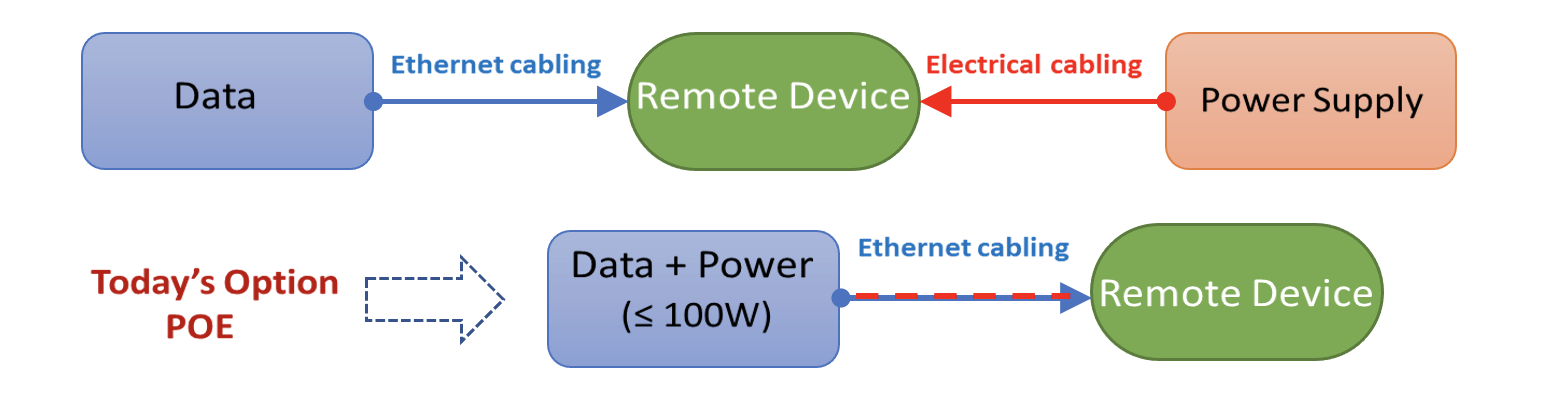
Power Over Ethernet (POE) technology as the name suggests it feeds functioning power to communications equipment from a source on a balanced twisted pair cable along with ethernet data communication signals. Amazingly, a single cable supports two services at a time making it more resourceful.
Our reliance on information through digital networks, making us to implement devices remotely like wireless Access points, surveillance cameras, access controls, IP speakers, digital signage, IoT etc., which are required to be activated and controlled for operation. Powering these devices in earlier days would have required a separate electrical cabling with additional cost. Today with POE technology, communication cabling can be used to deliver DC power remotely & avoid extra electrical cabling.
The Technology
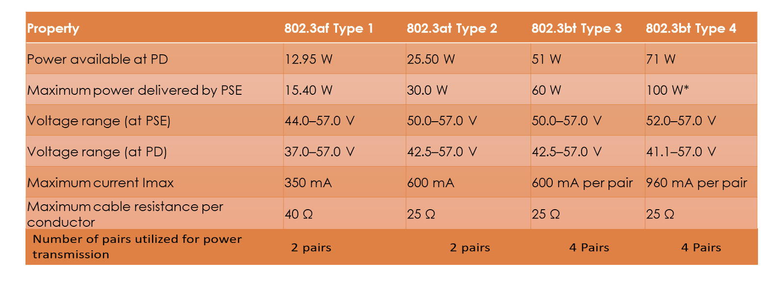
A power sourcing equipment (PSE) delivers the power to a Powered Device (PD) connected remotely via ethernet cables. Category 5e & above are recommended for such applications. TIA-TSB-184-A specifies the guidelines for supporting power delivery over balanced twisted pair cabling. IEEE Standards have evolved and recommended various capacities of POE. Here is a glimpse of it.
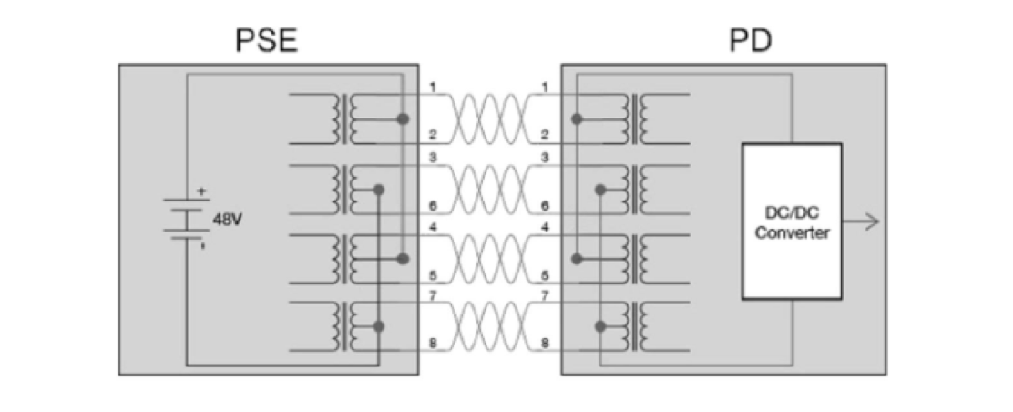
PoE is transmitted by applying a common-mode voltage on two or four pairs i.e. the current is evenly split between the two or four conductors. For this to happen, the DC resistance of each conductor in the pair must be balanced (equal), and any difference is referred to as DC resistance unbalance. Too much unbalance can distort data signals, causing bit errors, retransmits and even nonfunctioning data links. Also, excessive DC resistance unbalance between multiple pairs can also wreak havoc on data transmission or cause PoE to stop functioning.
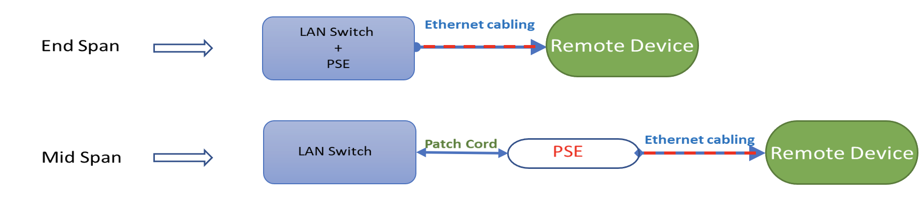
Two designs are available in terms of injecting power over the ethernet cables. One of them is called “End Span” where the data communication equipment also supplies the required DC power to the remotely connected Powered device (PD). The other one is called “Mid Span” where the data communication equipment does not supply power and a Power Sourcing Equipment (PSE) is placed in the middle of the cable channel to inject power onto the cable. These pictures say it all.
Considerations
When current is flown in ethernet cables, there will be a raise in temperature of the cable. And if the cables are bundled, as it normally happens in laying, the increase in temperature is significant. This may lead to derating of channel lengths as it increases attenuation for data transmission. A clear planning is required in selection of cable category, type of cable, bundle sizes, and path ways while designing POE application. Considering to reduce the bundle sizes to 24 cables is a good idea as it improves heat dissipation. Path ways should accommodate these bundles side by side with air gaps. Shielded cables has less temperature increase and better performing in this type of application.
Another factor to understand is that while un-mating the jack and plug on load will cause contact arcs and may affect connecting hardware reliability. Arcing can result in corrosion and pitted damage on the platted surface of the contacts at the arcing location. So, if the contact area is away from the arcing area, it will be safe.
Verification
After the installation of the cabling network, it is prudent to verify whether they can support POE. Conductor DC Resistance issues can cause overheating, power loss or data loss. Most of the cable testers available in the field today can measure DC Loop Resistance, Pair Resistance unbalance & Pair-to-pair Resistance unbalance. These parameters are not included in the declaration of “Pass” or “Fail” of the Permanent Link or channel testing. It is a good practice to validate these readings and ensuring unbalance are well within the limits of 0.2 Ω.