Estimating the Attenuation on the Optical Fiber Link
What is Attenuation?
Attenuation is a measure of the loss of signal strength or light power that occurs as light pulses propagate through a run of multimode or single-mode fiber. Measurements are typically defined in terms of decibels or dB/km.
The new 10g ethernet showcases full-duplex point-to-point links. These are generally connected by network switches shared-medium. It has not been carried over from the previous Ethernet standards. This is why half-duplex operation and repeater hubs are not a part of it. The 10 Gigabit Ethernet standard encompasses several physical layers, also known as PHY. This version of ethernet can use both copper and fiber cabling. The bandwidth requirements and higher-grade cables are a few reasons the maximum distance over a copper cable is 100 meters.
Wavelength:
The most common peak wavelengths are 780 nm, 850 nm, 1310 nm, 1550 nm, and 1625 nm. The 850 nm region, referred to as the first window, was used initially because of the support for the original LED and detector technology. Today, the 1310 nm region is popular because of the dramatically lower loss and lower dispersion.
You can also use the 1550 nm region, which can avoid the need for repeaters. Generally, performance and cost increase as wavelength increases.
Multimode and single-mode fibres use different fiber types or sizes. For example, single-mode fiber uses 9/125 um and multimode uses 62.5/125 or 50/125. The different size fibres have different optical loss dB/km values. Fiber loss depends heavily on the operating wavelength. Practical fibres have the lowest loss at 1550 nm and the highest loss at 780 nm with all physical fiber sizes (for example, 9/125 or 62.5/125).
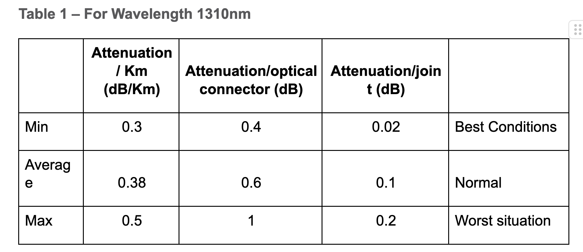
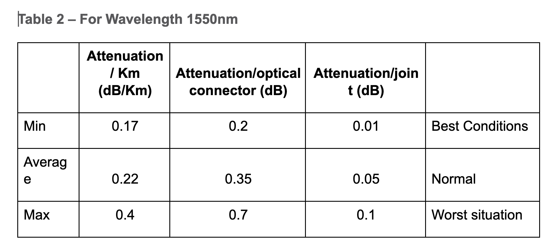
When you start to calculate the maximum distances for any optical link, consider tables 1 and 2:
Here is an example of a typical situation in the field:
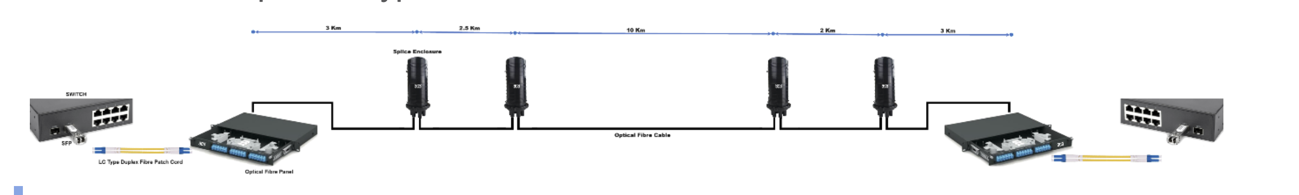
Estimate the Attenuation on the Optical Link
You can now calculate the attenuation for this link. You can arrive at the total attenuation (TA) of an elementary cable section as:
TA = n x C + c x J + L x a + M
-
where:
- n—number of connectors
- C—attenuation for one optical connector (dB)
- c—number of splices in elementary cable section
- J—attenuation for one splice (dB)
- M—system margin (patch cords, cable bend, unpredictable optical attenuation events, and so on, can be considered around 3dB)
- a—attenuation for optical cable (dB/Km)
- L—total length of the optical cable
When you apply this formula to the example, and assume certain values for the optical cards, you obtain these results:
For wavelength 1310nm: Normal
TA = n x C + c x J + L x a + M = 2 x 0.6dB + 4x 0.1dB + 20.5Km x 0.38dB/Km + 3dB = 12.39dB
For wavelength 1310nm: Worst Situation
TA = n x C + c x J + L x a + M = 2 x 1dB + 4x 0.2dB + 20.5Km x 0.5dB/Km + 3dB = 16.05dB
For wavelength 1550nm: Normal
TA = n x C + c x J + L x a + M = 2 x 0.35dB+ 4x 0.05dB+ 20.5Km x 0.22dB/Km+ 3dB = 8.41dB
For wavelength 1550nm: Worst Situation
TA = n x C + c x J + L x a + M = 2 x 0.7dB+ 4x 0.1dB+ 20.5Km x 0.4dB/Km+ 3dB = 13dB
Assume that the optical card has these specifications:
Tx = -3 dBm to 0dBm at 1310nm
Rx = -20 dBm to -27 dBm at 1310nm
In this case, the power budget is between 27 dB and 17 dB. If you consider the worst card, which has the power budget at 17 db at 1310nm, and the worst situation for the optical link to be 16.05dB at 1310nm, you can estimate that your optical link works without any problem. In order to be sure of this, you must measure the link.